
Marine engine mounts, which are made of steel plate with rubber or elastomer insert, have three functions:
- Transfer the thrust from the propeller to the vessel moving the vessel either forward or astern. (Some vessels have a thrust bearing which transfers the thrust directly to the hull of the vessel, so that it does not pass through the transmission or engine mounts.)
- Absorb vibration, thereby reducing noise.
- Secure and support the engine.
One size does not fit all. Mounts are sized according to the power and weight of the engine. Horsepower is an approximation for the thrust produced by the propeller (all things being equal). The weight of the engine indicates how stiff the rubber of the mounts needs to be.
If the rubber is too hard, less engine vibration is absorbed creating more noise and potentially causing something to break. The energy of the vibration must go somewhere.
However, if the rubber is too soft, the vibration of the engine can be amplified through the transmission and propeller shaft—leading to more noise and potential damage.
Engine mounts need minimal maintenance (grease on the threads to prevent rust) but should be inspected every three months. And care should be taken to keep grease, diesel or oil off the rubber.
The rubber deteriorates with engine use over time, eventually causing the engine to sag and to go out of alignment. A rule of thumb is to replace the mounts in pairs every 10 years. Always change mounts in pairs, never singly, to avoid creating uneven vibration.
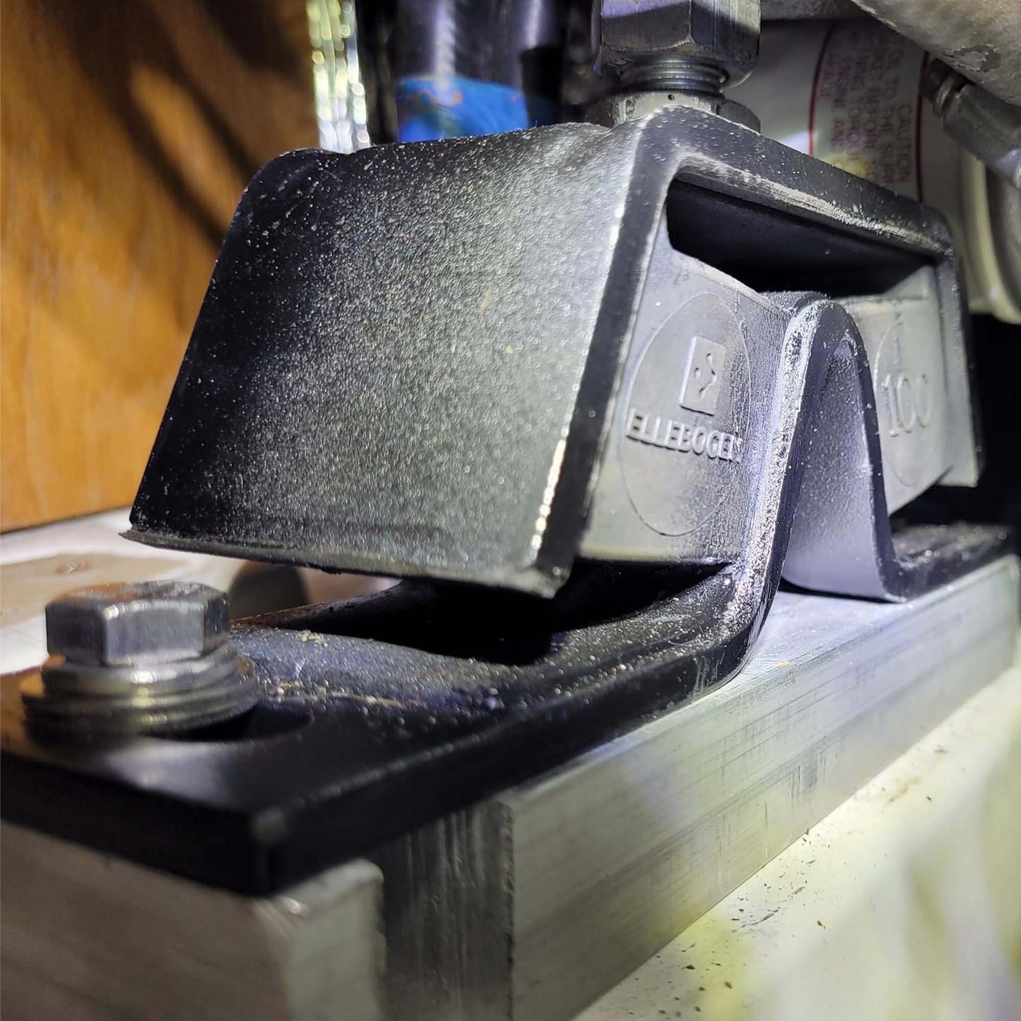
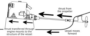 Figure 1
Badly rusted mounts can be cleaned with a wire brush and sprayed with penetrating oil or WD-40. With enough leverage from a pair of wrenches, it may be possible to loosen the nuts. With frozen, rusted nuts, it may be easier to unbolt the engine bracket (one at a time) so that the job can be tackled on a workbench and not in the confines of the engine compartment. Rusted mounts should be replaced when possible.
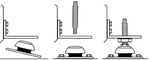 Figure 2 Installing engine mounts with a detachable stud.
Engine mounts with a detachable stud are the easiest to change. The bolt is unscrewed and the base can be removed without needing to lift the engine (which requires uncoupling the prop shaft from the transmission coupling). Alignment will still need to be verified but the process of aligning is much simpler because less has been disturbed.
While replacing engine mounts, the engine beds themselves should be inspected. An engine can’t be correctly aligned if the engine beds are soft or if the mounts are not firmly attached to the beds. Wooden engine beds may be internally rotten; lag bolts can vibrate loose.
Engine brackets should sit approximately at the mid-point of each engine mount stud. Too low—there may not be the vertical distance to adjust engine height to correctly align the engine. Too high—increased leverage puts extra pressure on the rubbers of the engine mounts and increases vibration.
The studs should be straight and perpendicular to both the engine brackets and the engine beds; if not, extra stress is created, which will likely lead to premature failure.
If the mounts are too low (ie. the brackets sit too high on the studs), solid spacers can be inserted under each engine mount. These should be slightly larger than the footprint of each mount and—critically—made of a non-porous material, such as a polyurethane block. Encasing wood in epoxy is acceptable but not ideal because of the potential for the epoxy to crack and allow moisture to degrade the wood.
If the engine brackets sit too low on the studs, either the engine mounts are too high or the engine brackets are too low. This can prevent correct engine alignment. Sometimes, the height of the brackets on the engine can be raised by drilling new, higher bolt holes in the brackets.
If this is not possible, the height of the engine beds may have to be reduced, either by physically cutting off the tops or by adding step-downs.
Three nuts and two strong, correctly sized washers should be used on each stud to support and secure each engine bracket:
A wide washer under the engine bracket helps spread the weight.
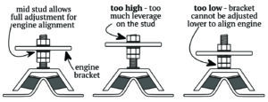 Figure 3
Use two nuts below the engine bracket—one locks against the other to stop the nuts loosening and rotating down the threads of the stud.
A second washer and the third nut are tightened above the engine bracket.
Make sure the mounts are tightly secured to the engine beds. Each mount should take an equal share of the weight of the engine, unless the engine installation manual instructs otherwise. This can be assessed by loosening the bolts on each stud, one at a time, then tightening in two stages:
- Hand tighten the bottom nut against the washer under the engine bracket.
- Give half a turn on the nut with a wrench so that the nut and washer are taking the weight but not lifting the engine bracket. The aim is to distribute the weight of the engine equally between the (four) engine mounts, with about 60 percent of the weight on the aft mounts. (This can be felt approximately by the force required on the wrench to raise the brackets).
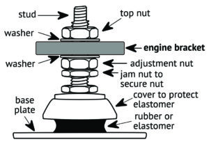 Figure 4
Raising (or lowering the engine) is part of aligning the engine, which comes after the new mounts have been successfully installed. Grease the threads of the studs and enter the details in the vessel’s Maintenance Logbook.
Dennison Berwick is author of Marine Diesel Basics 1, Maintenance, Lay-up, Winter Protection, Tropical Storage, Spring Recommission and the value-added Maintenance Logbooks for single and twin-engine installations. He sails a 1982 Chevrier 36, currently anchored in east Africa, and intends to sail from Tanzania to South Africa and across the Atlantic to Brazil in spring 2024.